Normally this blog is focused on software development – sometimes big ideas, sometimes small tips based on things I’ve learned recently. This post is different – it’s about about one of the things that kept me from writing either sort of post.
The Belkin KVM I’ve had for a number of years developed a habit of suddenly going nuts. Without warning it would start changing which monitor was connected, rebooting itself repeatedly, or just turning itself off. Wiggling the power cord didn’t do much but wiggling the power plug did, and the power socket seemed a bit loose. So I decided to open it up to see if there was a questionable solder joint to the power socket.
That’s when the fun began.
The case does not have any visible screws, so I figured it must be held together with snaps. I hate snaps because the sound of a snap opening normally and the sound of a snap breaking off are almost the same.
I pried open both sides but the middle of the case didn’t want to open up. I had previously checked under one of the rubber feet, since screws are often hidden there, and not found any. But then I realized I had checked under a back foot, but what about a front foot? Sure enough, there are screws hidden under both front feet.
With those screws remove the sides were loose but the middle was still holding tight. There’s an area on the bottom that I had thought was a molded feature, but it could be a label that matched the case. So with nothing to lose I started at a corner, and sure enough it was a label. Prying it up revealed 2 more screws on the right-hand end, and by symmetry there were two more near the left-hand end. The middle still held, until prying the label up further revealed another screw in the very middle.
So there are a total of 7 screws and 7 snaps. Why, Belkin, why? It’s not like anyone looks at the bottom of a KVM when it’s sitting on a desk. And the bottom has a serial number sticker and a “QC passed” sticker that aren’t attractive.
Here’s a view of the bottom, showing the label with 3 of the screws underneath it. The other two are in matching locations on the right. This view also shows the screw from under one of the front feet.

This view shows the inside once the bottom cover is finally removed. You can also see one of the plastic snaps at the left end. You would see two, but that snap didn’t survive. Oh well, 6 out of 7 isn’t too bad…
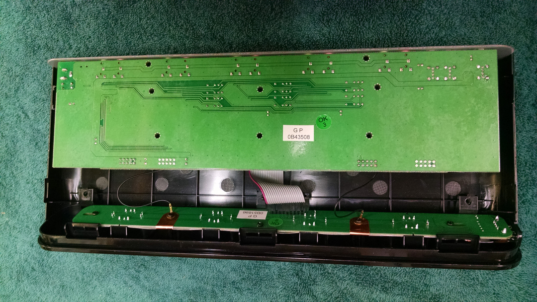
This view shows the inside after removing the bottom circuit board to work on it. This is as far as I went.

I had hoped to install resistors in series with the LEDs so they wouldn’t be so annoyingly bright, but the LEDs are soldered straight to the front circuit board. I didn’t want to get into cutting traces.
After removing the bottom circuit board I heated the connections to the power socket and flowed more solder in. I did the same for the two inductor/choke components next to it. After a week of daily use I’m happy to report no more problems.